There is a plethora of articles, discussion threads and other resources that presume to give advice on the issue of floor loading with heavy gun safes. Some of them even provide professional engineering counsel, even if they don’t say so. For instance, some articles I have seen mention the typical and customary floor design loading limit of 40 pounds per square foot (PSF) and then opine something like “but even though the load for a safe is concentrated in a small space, since the total floor surface area is much larger than the surface area the safe occupies and that isn’t loaded with the same weight, the gun safe load should be just fine,” or something like that.
I won’t say much more about those articles, except that it is extremely ill-advised to follow such ridiculous counsel, and unless it was crafted by a registered professional engineer specifically for your situation, you should ignore most if not all such articles. While I am a registered PE, what follows doesn’t constitute engineering advice for your specific situation or any specific situation for that matter (see the disclaimer below), but it might be instructive and beneficial for education to demonstrate and explain what I did to ensure my home was protected both from catastrophic failure and deleterious deflection and sagging of floor joists over time.
While some articles appear to downplay the significance of floor joist loading, I have been inside homes and seen sagging floors (that had not – or had not yet – catastrophically failed). While I considered the so-called “heavy load path” for transporting the gun safe inside the house, perhaps the more significant issue has to do with floor loading over time.
In order to provide the necessary background to understand the plans, the gun safe weighs in at just over 600 pounds. The measurements are 20″X33″X59″, so the floor loading significantly exceeds the design floor loading of 40 PSF.
The home is a new home built with pier and girder, with “engineered” joists. Engineered joists can span a much longer distance that traditional joists, and have no bracing or blocking. The joists sit either on girder (for spans) or ledger strip (at the edges). It obviously mattered to the builder that this large piece of granite in the kitchen:
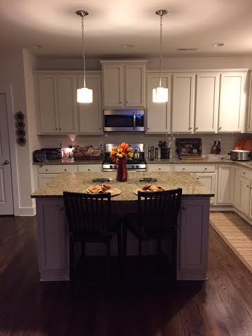
Exceeded the allowable floor loading of 40 PSF, so this girder sits underneath the large rock.
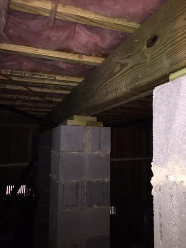
The kitchen shown above is in the Northerly direction, and the picture of the garage wall below looks East.
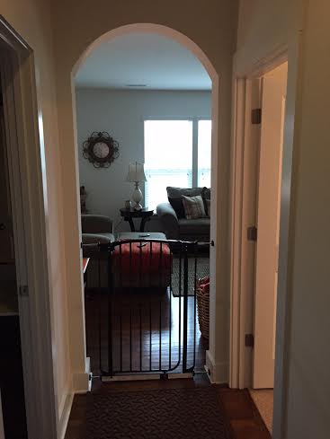
This is the hallway down which the safe was moved from the garage to the room on the right. The girder also sits under the hallway about three feet from the doorway to the garage, minimizing joist span for the move.
Right behind the garage wall is a room that has a closet, this closet being the intended final resting place for the gun safe. The floor joists are oriented East-West, and the support girders are oriented North-South. Placing the gun safe in this closet (which is centered at the North end of the room against the hallway wall, directly to the right as you stand in the picture above), means that I will be sitting the safe cantilevered along a joist several feet from the ledger strip. Furthermore, if I was going to position the safe facing East-West, the aspect ratio means that I could sit it along two joists (recall that the joists are 16″ on center). But I intended to position it facing South. Thus in my judgment I needed to construct a girder North-South, directly under the safe. Ron Hiatt, PE, helped my draw up the plans, although the plans as implemented have slight modifications compared to what was originally conceived.
The first step was to measure and lay out the girder, including plumb lines showing where I needed to dig my footings.
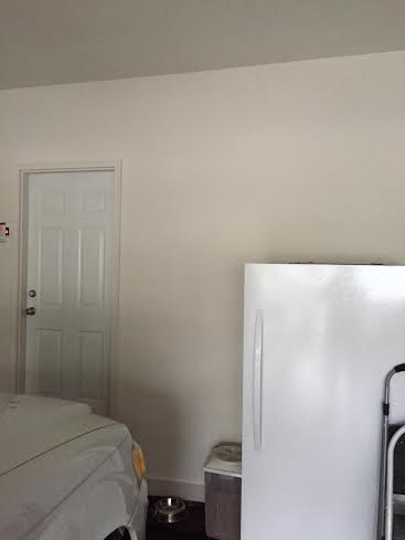
This picture shows the wall separating the garage and room which will house the gun safe. The door to the left is the door to the hallway shown above, and a right turn takes me into the room which contains the closet which has the safe.
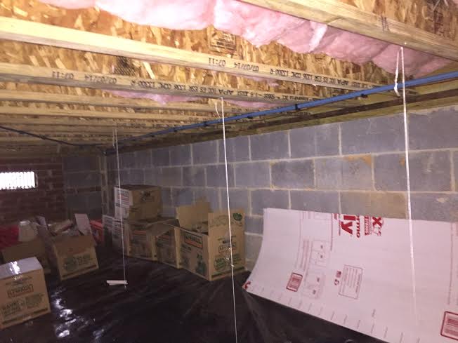
Plumb lines showing intended location of footings.
Cut a hole in the vapor barrier and dig footings, this step being especially difficult with limited room under the house.
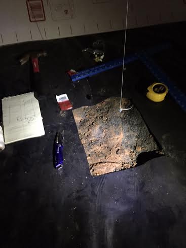
Each of the three footings were at least 1 cubic foot in volume.

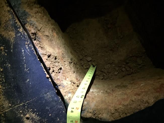
The footings were slightly deeper than 1 foot.
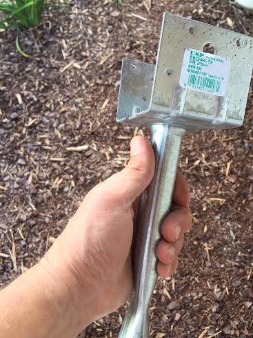
These are used to anchor the 4″X4″s, placed directly into the concrete, flush with the top of the finished concrete and directly under the plumb line.
I had to use 300 pounds of concrete, which I mixed right in the holes (requiring slightly more water than the bags called for). Use shims to ensure that the 4″X4″s are plumb, and then anchor the column with a 1″X2″ brace attached with a drywall screw to the joist above it.
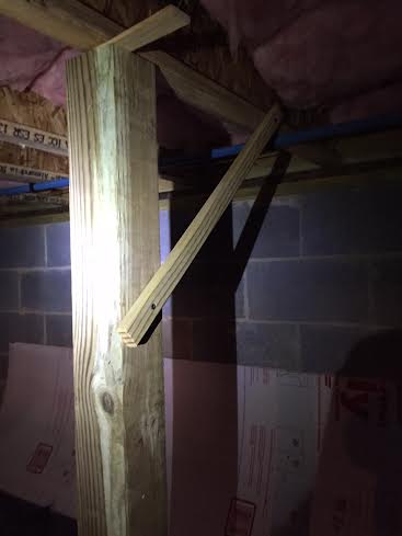
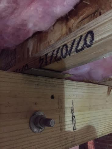
Attach two ten foot 2″X6″ girder pieces to the 4″X4″s using carriage bolts, aiding with drywall screws. I like to use screws since they can be installed cleanly (pre-drilled, avoiding cracks and splits), and use of a nail gun might have knocked the 4″X4″ out of plumb.
Use metal shims where you can, as has become commonplace with new home design between pier and girders.
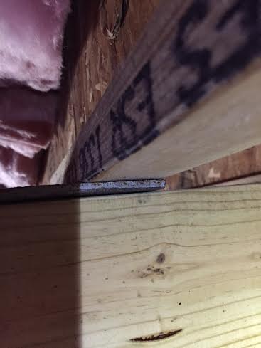
Here is another picture of shimming.
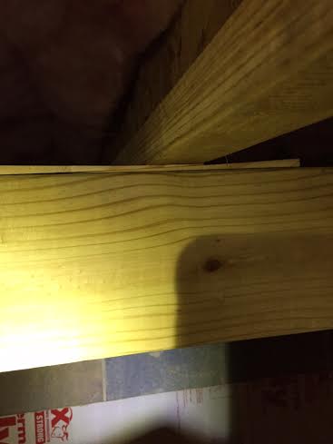
In other places, use standard wood shims depending upon clearance.
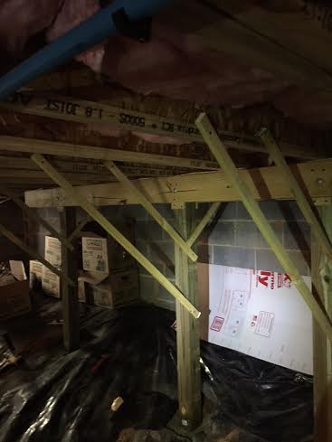
The final girder looks like this, running North-South and with additional 1″X2″ bracing because I had the additional wood.
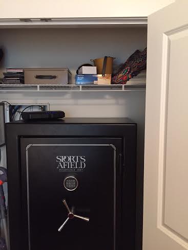
The safe in its final resting place in the closet looks like this, sitting directly on top of the new girder and against the hallway wall.
During the move, the safe at all times (a) was directly over the girder, or (b) directly over doubled-up joists (two engineered floor joists at the load bearing walls), or (c) not more than approximately three feet from the girder or doubled-up floor joists. The total time in transit from the garage to the closet was approximately two minutes.
The total investment in components and parts represents approximately $150. This is a small fraction of the cost of the home. Guns and safes represent a significant investment of time, money and energy. Don’t do them haphazardly. Homes represent a much larger investment. Don’t destroy either one with a safe that is too heavy for the design. Think. Plan. Execute. Hope is not a plan.
Disclaimer: This article does not constitute engineering advice. The plans shown and discussed above are not necessarily adequate or appropriate for all or even any specific circumstances. There is no warranty, express or implied, in the plans discussed herein. The liability for any application or use of said plans rests solely with the user and not with the author. In any use of said plans, or any plans based on, analogous to or any modification thereof, the user specifically indemnifies the author and understands that he is alone responsible for any and all damage. The author doesn’t assume responsibility for any damage – catastrophic or gradual – to any structures, systems or components resulting from these plans.


